Non inductive co-axial current shunt
 Current viewing resistor (CVR) Series A
Powertek
UK Tel: +44 1788 519911
US Tel: +1 631 615 6279
Email : info@powertekus.com
Email : info@powertekuk.com

return to homepage | info@powertekuk.com | contact us


Series A non inductive co-axial current shunt


  • 0.01A to 100Arms continuous

  • 1000Arms for 10mS (depending on model)

  • DC-100 MHz frequency range

  • Extends current range of Scopes, DMMs and
    Wattmeters

  • Use with phase angle meters

  • BNC, GR, UHF, N, HN and C connectors

  • Insulated enclosure optional
  • Traceable to international standards via NIST (USA) and UKAS (UK)
  • Lifetime warranty

About the Series A current viewing resistor (CVR) / non-inductive co-axial shunt resistors

The Series A range are non inductive shunts designed to operate over a wide bandwidth, with both AC and DC power systems, especially where phase angle is a consideration, crucial during impedance measurements and power calibration systems.  Very useful for adding or extending the current range of Frequency Response Analyzers and Multimeters.  The Series A can be used with phase angle meters, where phase angle between voltage-voltage, voltage-current or current-current is required, ideal for phase protection, power meters, wattmeters, energy meters and current transformer calibration.

CVR's are rugged high frequency resistors designed to sustain very high peak power and current inputs generated by capacitor banks, pulse generator systems and steady state current loads.  Their linear response over a broad frequency band provides an accurate indication of current magnitude free from inductive components.  Inherent in CVR design is a coupling between the major electrical parameters of resistance, bandpass, energy capacity and wattage rating.  This means we provide a wide ranging series of standard units covering a broad range of specifications.


WATTAGE RATING

Although most CVR's are designed primarily for surge current measurements, their rugged construction and their low temperature coefficient resistive elements have made them ideally suited to a number of steady state applications.  An average wattage rating applicable to continuous current loading is thus quoted for each resistor series.   Care should be taken in circuitry involving either AC or high duty cycle pulse currents that this rating not be exceeded, since CVR damage by overheating can result.   If requested we can supply resistors with special construction which will increase the standard wattage rating to a high value depending on the model.


FREQUENCY RESPONSE

Bandpass of a CVR is essentially flat from DC to an upper limit determined primarily by skin effect in the resistive element.  Associated bandpass is based on a measured 10% to 90% risetime response to a step function of current produced by a coaxial line pulse generator.  The di/dt of the test pulse exceeded 10^12 amps/sec.


RESISTANCE VALUES

Unless otherwise specified, resistors are supplied with resistance tolerance of ±4% of nominal value.  In addition, a Kelvin Bridge determination of its exact resistance, accurate to ±0.2% is supplied with each unit.  A wide range of special resistance values for any of our
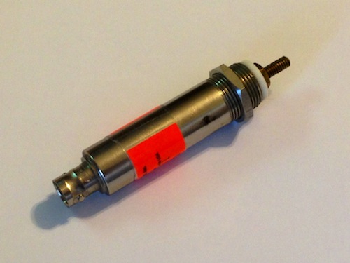
 standard units can be supplied.


MECHANICAL DESIGN

Case construction of all coaxial CVRs is silverplated brass.  Standard output signal connector is BNC with other connectors available.  Large coaxial CVRs utilize a high current flange and coaxial threaded stud input connections.  Powertek's flat configuration CVRs, the Series W, originally developed for flat plate transmission line installation, are available in a wide range of unit widths and input configurations and have been found to be particularly useful in applications requiring resistors with extreme energy and wattage ratings.


World-wide Traceability

All measurements made using the CVR series A shunts are traceable to National and International standards; through the measurement standards of Powertek. All CVR series A shunts are supplied with a certificate of conformance necessary for quality assurance standards such as IEC17025/ISO9001. Independent measurement certification is possible using UKAS, A2LA or Z540/NAVLAP certificate.


Non inductive shunt - CVR applications

  • Pulsed current applications

  • Calibration laboratories

  • Current sensing for phase meters

  • Single phase angle indicators V-A

  • Three phase phase angle indicators V-A

  • Cos Phi indicators

  • Power factor meters

  • High Frequency Watt Meters

  • Wideband Power meters

  • Power analysis

  • Current transformer calibration

  • Current probe phase delay

  • SCR current measurements

  • Current control of automatic welders

  • Measure output of automotive alternators

  • Fault current detection to determine bearing
    wear of steam turbine generators

  • EBW testing

  • Current detection in detonation systems

  • Three-phase fault testing in power
    transmission substations

  • Fault detection in modulators

  • Measurement of laser system currents

  • Chopper current control in electric cars

  • Circuit breaker testing


SERIES A CURRENT VIEWING RESISTORS SPECIFICATIONS


WIDE BANDWIDTH - HIGH FREQUENCY - ULTRA LOW PHASE SHIFT

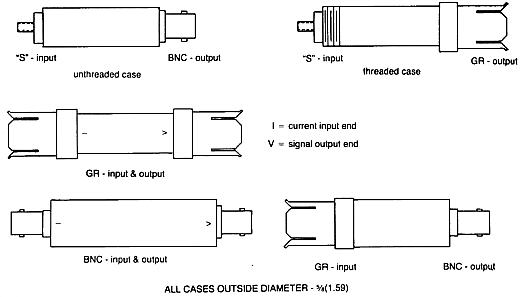
Small terminating type CVR available with BNC, GR, UHF, N, HN and C connectors.

Other connector options available upon request. Standard connections are the "S"

input (8-32 stud with threaded case) BNC output connector.


SPECIFICATIONS

4 Watt Units - 3 1/4 Inch Case*

Model

Resistance ohms

Bandpass MHz.

Risetime nsec.

Emax joules

A-2-01

0.01

400

1

16

A-5-05

0.05

2000

0.18

5

A-2-005

0.005

200

2

15

A-4-0025

0.0025

48

8

30

A-8-001

0.001

12

30

70


5 Watt Units - 3 1/8 Inch Case*

Model

Resistance ohms

Bandpass MHz.

Risetime nsec.

Emax joules

A-1-05

0.05

1200

0.30

20

A-2-025

0.025

400

1

40

A-5-1

0.10

1200

0.30

10

A-4-005

0.005

48

8

60


6 Watt Units - 5 Inch Case*

Model

Resistance ohms

Bandpass MHz.

Risetime nsec.

Emax joules

A-1-1

0.10

800

0.45

40

A-2-05

0.05

400

1

80

A-5-2

0.20

1200

0.30

20


7 Watt Units - 5 1/2 Inch Case*

Model

Resistance ohms

Bandpass MHz.

Risetime nsec.

Emax joules

A-5-5

0.50

800

0.45

15


*Case lengths are for the SBNC-X-X model type, case lengths for other connectors

will vary slightly.  "S" modification - Current input connection is an 8-32 stud with the

case threaded 5/8-24, supplied with two nuts.  Unthreaded case available if specified.


S03.jpg (19949 bytes)


ORDERING INFORMATION

When ordering specify model number, input and output connector or connections and tolerance.
Example: SBNC-2-01, 4%
 

Return to homepage