|
|
|
I-Probe IP520 Non-Contact Current Probe Datasheet
I-Probe IP520 current probe Specifications |
|||
| Output Signal | |||
| Maximum Output | 10V | ||
| Oscilloscope Inputs | Suitable for an input impedance of 1MΩ in parallel with <30pF | ||
| Trace Position | Wide range DC offset control within signal conditioner | ||
| Safety | |||
| Max. Circuit Voltage | 300V Cat II (on AC line circuits). 600V Cat 1 (on uncategorized circuits inside equipment) | ||
| Max. Tip Temperature | 150�C maximum allowable temperature at probe tip | ||
| Conformance | Complies with EN61010-1 and EN61010-031 | ||
| Bandwidth Control | |||
| Switch Position | Full | 500kHz | 2Hz |
| Nominal Bandwidth | DC to 5MHz | DC to 500kHz | DC to 2Hz |
| Risetime | <70ns | 700ns | 175ns |
| Aberrations | < �5% | < �1% | < �1% |
| Noise (Typical)* | 6mA rms | 3mA rms | 1.5mA rms |
| *This is the noise level for current measurement using the Toroid attachment. For PCB track measurement the equivalent noise will depend upon the track width and gain setting but will be similar to the Toroid measurement figure for a track width of 0.5mm. | |||
| HF Performance | |||
| Propagation Delay | 60ns typical (to 10%) | ||
| Bandwidth | DC to 5MHz (small signal) | ||
| Slew Rate | 15A/us (equivalent) | ||
| Overload Indication | |||
| Indicator Threshold | Indicator LED within signal conditioner will light if output voltage exceeds +/- 10V or if large magnetic fields cause the system to saturate | ||
| Power Source | |||
| Power Supply | 5.2V at up to 5 watts from AC line adaptor (supplied) | ||
| Mechanical | |||
| Probe Dimensions | 155mm x 38mm x 28mm max; 2.8mm x 1.8mm at tip | ||
| Cable Length | 2m from probe tip to output BNC | ||
| EMC | |||
| Conformance | Complies with EN61326 | ||
| Magnetic Field Measurement (Mode = Field) | |||
| Scaling Factor | 250uT (or 200A/m) per Volt. | ||
| Accuracy and Linearity | �3% | ||
| Maximum Field | �2.5mT (2000A/m). | ||
| Current Measurement using Toroid (Mode = Wire) | |||
| Scaling Factor | 1 Amp per Volt. | ||
| Accuracy and Linearity | �5% | ||
| Current Range | �10mA to +/-10A (DC + peak) | ||
| Max. Wire Diameter | 3.5mm (unbroken) or 6mm (end fed) | ||
| Current Measurement in PCB Tracks (Mode = PCB Track) | |||
| Scaling Factor | Adjustable to 1 Amp per Volt for track widths 0.2mm to 3.5mm (0.007" to 0.14") and 2 Amp per volt for track widths 3mm to 6.5mm (0.125" to 0.25") using Calibrator and compensation graph. | ||
| Sensor Spacing | 0.7mm distance from sensor to PCB track set by probe design. | ||
| Calibrator | Built-in calibrator within the signal conditioner providing an AC or DC calibration current through a 0.5mm track | ||
Using the I-Probe IP520 non-contact current probe |
|
| What's supplied? |
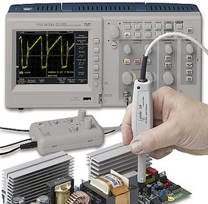
The I-Probe IP520
consists of the current probe connected by
1.25 metres of cable to its signal conditioner. From there a further
0.5 metres of cable is terminated in a BNC connector for use
with any normal oscilloscope. |
| The Signal Conditioner |
The signal
conditioner provides the choice of three modes of operation
along with bandwidth filters, an offset control and overload
indicator. |
| PCB track current measurement |
The unique feature of the I-Probe
IP520 is its ability to observe and measure currents flowing in
PCB tracks by acting as a non-contact current probe. |
| Closed-loop current measurement (in a wire) |
Whereas the primary purpose of the
I-Probe 520 is as a positional current probe, the are many
circumstances where current measurements can be made in the
conventional way by enclosing the conductor. |
| Measurement of electromagnetic field |
The very small size of the field
sensor within the IP520 gives it some unique capabilities
when used to measure magnetic fields. |
