|
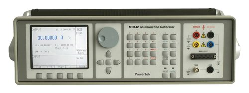
MC142 Multifunction Calibrator 15 ppm basic accuracy |
Powertek |
return to homepage |
info@powertekuk.com
|
contact us
|
Multifunction calibrator MC142 is a precision voltage, current and power calibration source serving as a measurement standard in calibration laboratories and production lines; where verification of electrical measurement equipment & sensors is required. It can be used for calibration and adjustment of meters measuring voltage, current, power, resistance, capacitance and frequency. Internal harmonic and non-harmonic signals make it possible to test electrical performance of meters using signals with various crest factors. Frequency modes enable selection of frequency, amplitude and duty cycle of the output signal. These are suitable for basic calibration of digital and analog oscilloscopes along with transient recorders. The calibrator is equipped to measure temperature with TC and RTD temperature sensors. Its built-in multimeter can be used independently or simultaneously with the calibrator output. Testing of transducers of various types, regulators and sensors can be performed, without the necessity to use any other measuring instrument. |
MC142 multifunction calibrator is available |
|||||||||||||||||||||||||||||||||||||||||||||||||||||||||||||||||||||||||||||||||||||||||||||||||
LinksMC142 datasheet | MC142 User Manual | MC142 Brochure| MC142 Options/AccessoriesFront Panel Display | Front panel terminals |
||||||||||||||||||||||||||||||||||||||||||||||||||||||||||||||||||||||||||||||||||||||||||||||||||
|
Basic function of the calibrator is the generation of calibrated DC/AC voltage in the range from 0�V to 1000V and DC/AC current in the range from 0 to 30A. Using a 50-turn coil the current range can be extended to 1500A. The best accuracy of the calibrator on DC voltage ranges is 15ppm, on AC voltage ranges 250ppm, on DC current ranges 130ppm and on AC current ranges 550ppm. Maximum frequency range is from 20Hz to 100kHz for harmonic output waveform. The calibrator is equipped with a function generator for periodic non-harmonic signals with defined crest factor, making it possible to test sensitivity of multimeters to distorted signals. In addition the calibrator simulates resistance and capacitance, the resistance range from 0.0 Ohm to 1000MOhm and capacitance from 1nF to 100�F can be simulated exceeding the required precision for calibration of common hand-held multimeters. Basic accuracies are resistance ranges 150ppm and capacitance ranges 0.1%.Frequency function of the calibrator makes it possible to generate a square wave signal with adjustable and calibrated duty ratio, frequency and amplitude in range from 1mV to 10V in the frequency band up to 10kHz. In the mode HF the square wave signal up to 20MHz with a very low rise-time can be generated. The frequency functions are suitable for the calibrations of corresponding frequency ranges of the multimeters and for calibration of the channel sensitivities and time bases of the oscilloscopes as well.For calibrations of DC and one-phase AC power-meters and energy meters, the power � energy mode is determined. Output voltage can be set up to 240V and output current up to 20A with the power factor in range from -1 to +1 in the frequency band from 40Hz to 400Hz. Current capability of the voltage output is 30mA. It allows calibration of analogue power-meters which have higher current draw. For calibrations of the thermometers and temperature regulators, the function of simulation of temperature sensors is determined. Calibrator is able to simulate all common used Pt and Ni resistance sensors and TC sensors of the R, S, B, J, T, E, K and N types as well. Compensation of the TC cold junction is made either by entering value from the keyboard, or automatically by measuring the ambient temperature with Pt-100 sensor. The precision of the simulated resistance and TC sensors depends on set value and type of the sensor. For resistance sensors uncertainty band is in the range from 0.04�C to 0.5�C, for TC sensors from 0.4�C to 4.0�C. |
||||||||||||||||||||||||||||||||||||||||||||||||||||||||||||||||||||||||||||||||||||||||||||||||||
Built-in multimeter |
||||||||||||||||||||||||||||||||||||||||||||||||||||||||||||||||||||||||||||||||||||||||||||||||||
|
The MC142 internal multimeter has a basic capability to measure DC
current to 20mA,
DC
voltage to 10V, resistance to
2kOhm and frequency to
15kHz as standard. With accuracy of 100ppm it
enables measurement of output signals of various types of transducers. With
external TC or resistance temperature sensors, temperature can
be scaled, as can external strain
gauge sensors,
for pressure, torsion, strength, etc.
actual units can be
measured and displayed. |
||||||||||||||||||||||||||||||||||||||||||||||||||||||||||||||||||||||||||||||||||||||||||||||||||
Calibrator � Tester |
||||||||||||||||||||||||||||||||||||||||||||||||||||||||||||||||||||||||||||||||||||||||||||||||||
|
Calibrator can be used in simultaneous
mode, i.e. selected output signal is generated and the response
of the device under test is measured at the same time by internal multimeter. Programmable
capability of
the calibrator enables setting of 10 steps defined by output signal
function and output value on source side and awaiting response of DUT
measured by internal multimeter including allowed limits of the DUT.
The testing can run automatically. |
||||||||||||||||||||||||||||||||||||||||||||||||||||||||||||||||||||||||||||||||||||||||||||||||||
Ease of use |
||||||||||||||||||||||||||||||||||||||||||||||||||||||||||||||||||||||||||||||||||||||||||||||||||
|
MC142 Calibrator is equipped with a number of other functions which make its use easier. Among them belong possibility to set relative deviations from the actual value of the selected output signal, displaying of the output signal uncertainty, internal calibration procedure and others. Concept of the calibrator's control and indication uses a large area luminescence display on which all necessary information is concentrated. The control is perform by selection from the menu. Moreover, frequently used functions have firmly assigned keys with direct control. Normally, the calibrator is equipped with the GPIB bus and with the RS-232 serial port making it possible to be controlled by personal computer. The calibrator can be included into POWERTEK WinQbase/CALIBER software calibration systems. MC142 calibrator is derived from previous successful model MC-140. Against MC-140 model the new MC142 offers extended ranges and higher accuracy. |
||||||||||||||||||||||||||||||||||||||||||||||||||||||||||||||||||||||||||||||||||||||||||||||||||
|
Specifications |
||||||||||||||||||||||||||||||||||||||||||||||||||||||||||||||||||||||||||||||||||||||||||||||||||
|
||||||||||||||||||||||||||||||||||||||||||||||||||||||||||||||||||||||||||||||||||||||||||||||||||
| Voltage range: | 0 to 1000V |
| Frequency range: | 20Hz to 100kHz |
| Resolution: | 6½ dig. |
| Range | % of value + uV | % of value + uV | % of value + uV | % of value + uV |
| DC | 20Hz - 10kHz | 10kHz - 50kHz | 50kHz - 100kHz | |
| 0mV - 20mV | 0.005 + 6 | 0.2 + 30 | 0.20 + 30 | 1.0 + 30 |
| 20mV - 200mV | 0.0015 + 8 | 0.1 + 80 | 0.15 + 120 | 0.3 + 120 |
| 200mV - 2V | 0.0012 + 10 | 0.018 + 100 | 0.05 + 200 | 0.2 + 1000 |
| 2V - 20V | 0.0010 +50 | 0.018 + 1000 | 0.05 + 6000 | 0.2 + 10000 |
| 20V - 240V | 0.0015 + 500 | 0.018 + 10m | - - | - - |
| 240V - 1000V | 0.005 + 20000 | 0.03 + 200m* | - - | - - |
| Current range: | 0 to 30A |
| Frequency range: | 20Hz to 10kHz |
| Resolution Setting: | 6½ dig. |
| Range |
% of value + �A |
% of value + �A | % of value + �A | % of value + �A |
| DC | 20Hz - 1kHz | 1kHz - 5kHz | 5kHz - 10kHz | |
| 1�A - 200�A | 0.05 + 0.02 | 0.15 + 0.02 | 0.30 +0.22 | - - |
| 200�A - 2mA | 0.02 + 0.1 | 0.07 + 0.2 | 0.20 + 1 | 0.50 + 1.4 |
|
2mA - 20mA |
0.01 + 0.6 | 0.05 + 1 | 0.20 + 10 | 0.50 + 14 |
| 20mA - 200mA | 0.01 + 6 | 0.05 + 10 | 0.20 + 100 | 0.50 + 140 |
| 200mA - 2A | 0.015 + 100 | 0.05 + 100 |
- - |
- - |
| 2A - 20A | 0.02 + 2 000 | 0.10 + 6000 | - - | - - |
| 20A - 30A ** | [0.02 + 0.003* (I-20)] + 2000 | [0.1 + 0.003* (I-20)] + 6000 | - - | - - |
*I is set current in A. Additional accuracy with Opt.140-50 Current coil is 0.3%. Multiplying coefficient is 25 or 50. ** Maximal period for continuous current 30A is 30s. Maximal period for continuous current 20A is 60s.
Function Shape (non-harmonic signals)
| Voltage range: | 1mV to 200V |
| Current range: | 100uA to 2A |
| Wave form: | square positive, negative, symmetrical, saw A, B, triangle limited sin |
| Peak value accuracy: | 0.3% + 50uV |
| Displayed values: | peak, calculated rms |
| Frequency range: | to 1000Hz for voltage, to 120Hz for current |
| The lowest frequency for square waveforms is 0.1Hz, for other waveforms 20Hz. | |
Resistance and Capacitance
| Resistance range: | 0 to 1000 MΩ |
| Capacitance range: | 900pF to 100�F |
| Resolution: | 4 dig. |
Function Frequency
| Total frequency range: | 0.1Hz to 20MHz |
| Resolution: | 6 dig. |
| Accuracy of frequency: | 0.005 % |
| Frequency function modes: | - PWM, fmax = 100kHz, square waveform with calibrated ratio and amplitude |
| - HF, fmax = 20MHz, square waveform with calibrated frequency and amplitude | |
| PWM mode (0.1 Hz to 100 kHz): | |
| Voltage range | % of value + uV |
| 1mV - 20mV | 0.2 +50 |
| 20mV - 200mV | 0.1 + 50 |
| 200mV - 2V | 0.1 |
| 2V - 10V | 0.1 |
| HF mode (0.1 Hz to 20 MHz): | |
| Output impedance: | 50Ohm |
| Output waveform: | square symmetrical |
| Amplitude: | 4V pk-pk |
| Range of amplitude setting: | 0, -10, -20 dB, -30dB +/- 1dB |
| Amplitude accuracy: | 10% |
| Rise time: | < 5ns |
RTD temperature sensor simulation
|
Type |
Temperature range �200 - +250oC |
Temperature range 250 � 850oC |
|
Pt 100 |
0.1oC |
0.1oC |
|
Pt 200 |
0.1oC |
0.2oC |
|
Pt 1000 |
0.2oC |
0.4oC |
|
Ni 100 |
0.07oC |
--oC |
TC temperature sensor simulation
| J |
range [oC] |
-50 � 0 | 0 - 400 | 400 - 1000 | 1000 - 1767 |
| accuracy [oC] | 2.0 | 1.5 | 0.9 | 1.0 | |
| S | range [oC] | -50 - 0 | 0 - 250 | 250 - 1400 | 1400 - 1767 |
| accuracy [oC] | 1.8 | 1.5 | 1.0 | 1.0 | |
| B | range [oC] | 400 - 800 | 800 - 1000 | 1000 - 1500 | 1500 - 1820 |
| accuracy [oC] | 1.9 | 1.1 | 1.0 | 0.9 | |
| J | range [oC] | -210 - -100 | -100 - 150 | 150 - 700 | 700 - 1200 |
| accuracy [oC] | 0.6 | 0.4 | 0.3 | 0.4 | |
| T | range [oC] | -200 - -100 | -100 - | 0 - 100 | 100 - 400 |
| accuracy [oC] | 0.6 | 0.4 | 0.3 | 0.4 | |
| E | range [oC] | -250 - -100 | -100 - 280 | 280 - 600 | 600 - 1000 |
| accuracy [oC] | 0.9 | 0.3 | 0.2 | 0.2 | |
| K | range [oC] | -200 - -100 | -100 - 480 | 480 - 1000 | 1000 - 1372 |
| accuracy [oC] | 0.7 | 0.4 | 0.4 | 0.5 | |
| N | range [oC] | -200 - -100 | -100 - 0 | 0 - 580 | 580 - 1300 |
| accuracy [oC] | 1.0 | 0.5 | 0.5 | 0.5 |
Build in process multimeter
| Function | Range | Accuracy (%) | Resolution/Range |
| V DC | 0 - 12V | 0.01 + 300uV | 100uV |
| mA DC | 0 - 25mA | 0.015 + 150nA | 100nA |
| mv DC | 0 - 2V | 0.02 + 7uV | 0.1 - 10uV |
| Resistance | 0 - 2.5kOhm | 0.02 + 10mOhm | 1 - 10mOhm |
| Frequency | 1Hz - 15kHz | 0.005 | 10uHz - 100mHz |
| Temperature TC | -250 - 1820oC | 0.4 - 2.5oC | 0.01oC |
| Temperature Pt | -200 - 850oC | 0.1oC | 0.1oC |
General data
| Warm up time: | 60 min |
| Working temperature range: | 23 � 10oC |
| Stocking temperature range: | 0 to 40oC at RH bellow 80 % |
| Reference temperature: | 23 � 2oC |
| Dimensions: | 450 x 480 x 150 mm |
| Weight: | 23kg |
| Power line: 115/230 V |
Accessories (included)
| Power line cable | 1 pc |
| Operation manual, CD | 1 pc |
| Option 10/11 Test wire banana-banana 1000V-20A | 2 pcs |
| Option 40, 60, 70, 80 Cable adapters | 1 pc each |
| Spare fuse | 1 pc |
| RS232 cable | 1 pc |
| Option 140-50 | Current coil 25/50 turns | Calibration of clamp ammeters |
| Option 10 | Test cable 20A/1000V (black) | 1m length |
| Option 11 | Test cable 20A/1000V (red) | 1m length |
| Option 20 | Test cable BNC � BNC | 1m length |
| Option 30 | Test cable BNC � banana | 1m length |
| Option 40 | Cable adapter Canon 25 / 2 x bananan, 1m | DC current/voltage measurement |
| Option 60 | Cable adapter Canon 25 / 4 x banana, 1 m | 4W resistance measurement |
| Option 70 | Cable adapter | 4W resistance simulation |
| Option 80 | Cable adapter Canon 25 / 2 x banana | mV DC and TC temperature sensor measurement |
| Option 90 | External Pt temperature sensor | Pt 1000 probe |
| Option 100 | Cable adaptor for distance change between panel terminals to 3/4 inch |
 |
| Option 140-01 | Cable adapter with metal sheet for UUT easy connection | With built in temperature sensor |
| Cable GPIB | GPIB cable | 1m length |
| Cable RS-232 | RS-232, 2m | 1.5m length |
| WinQbase | Database application software | |
| CALIBER | Application SW for automated and semi automated calibrations. |
Links
MC142 datasheet | MC142 User Manual | MC142 Brochure
| MC142 Options/Accessories