Single Phase Frequency Converter AC Power Source
Lightweight 19" Rack mount chassis

Powertek
UK Tel: +44 1788 519911
US Tel: +1 631 615 6279
Email : info@powertekus.com
Email : info@powertekuk.com

return to homepage | info@powertekuk.com | contact us


Model 2U

Compact Chassis (1U – 4U Height)
Ultra Lightweight Design
50, 60 or 400Hz outputs
Power Factor Corrected Universal Input
Servers and SNMP Communications


Powertek's Ultra Lightweight Galaxy-Series Solid-State Frequency Converter Systems are high-reliability power sources specifically designed for demanding applications in high shock, vibration, humidity, and EMI environments in compliance to MIL-STD-1399, MIL-STD-461, MIL-STD-901, MIL-STD-167, MIL-STD-810, MIL-STD-740, and DOD-STD-1399. These models offer maximum field-proven reliability for severe environment and high reliability applications such as:

  • Military Applications: Including HMMWV, UAV,
       Shipboard, Submarine, Aircraft, Mobile Power Units,
       Shelters, Transportable Systems, Tactical Systems,
       Ground Support, and more.
  • Heavy-Duty Industrial Applications 
  • Demanding Commercial Applications 
  • Communications Systems
  • Power Conditioning
  • Export Testing


Model 4U

Click here for Single Phase Lightweight Solid Frequency Converter Datasheet
 

Specifications

ELECTRICAL
  • Input Voltage: 120/240 VAC Autoselect PFC (3� input optional)
  • Output Voltage: 120, 208, or 230 VAC (specify)
  • Frequency: 50 / 60 / 400 Hz
  • Voltage Regulation: � 2% no load to full load
  • Frequency Regulation: � 0.5% no load to full load
  • Harmonic Distortion: 5% THD, 3% typical
  • Input Power Factor: 0.95 or better @ half-full load
  • Efficiency at full load: 80-85% @ full load typical
  • Connections: MS Connector (mates opt.)
NOMINAL DIMENSIONS
  • Dimensions: 19″ Wide x 24″ Deep (See chart for height)
PROTECTIVE FEATURES
  • Input Circuit Breakers
  • Overload & Thermal Protected
  • Input Under/Overvoltage Protected
  • Optional Audible Alarm with Silence Switch
STANDARD REMOTE CONTACTS
  • SNMP V1.0 (Available-Optional) via CAT-5 Connector
  • Major Alarm: Logic Fault,, Overtemperature, Frequency Converter Overload
  • Minor Alarm: Utility Off
  • RS 232 (Available-Optional) Via DB 9 Connector
  • Alarm Contacts (Available-Optional)
INDICATORS
  • AC Input On
  • AC Output On
OPTIONAL AUDIBLE ALARM
  • Audible alarm with silence switch

Environmental

  • Operating Temp.: -20� to +50�C (Extended ranges optional)

  • Storage temperature range: -40� to +71�C

  • Humidity: to 95% RH non-condensing per MIL-STD-810. All boards conformal coated with Acrylic MIL-I-46058 Type R.

  • Elevation: 15,000 Ft. (4,572m) operating;
    40,000 ft. (12,192m) non-operating

  • Shock: 20g, 11 mS half sinewave per MIL-STD-810

  • Audible Noise: Less than 55 dbA at 5 ft.

  • EMI: MIL-STD-461

  • MTBF: 100,000+ hours per field data @ +25�C Ambient Ground-Fixed

  • MTTR: 30 minutes by qualified personnel


Partial Model Selection


60 Hz Output Models
Model KVA KW Nominal Input Input Freq. Output VAC Output Freq. F.C (Lbs) Height Outline Drawing
GLFCPFC-5K60-120/240A-120-4U 5 4 120-240VAC 50/60Hz 120 60Hz 45 4U pdf_icon
GLFCPFC-3K60-120/240A- 120-4U 3 3 120-240VAC 50/60Hz 120 60Hz 42 4U pdf_icon
GLFCPFC-3K60-120/240A-120-3U 3 2.4 120-240VAC 50/60Hz 120 60Hz 40 3U pdf_icon
GLFCPFC-2K60-120/240A-120-3U 2 1.6 120-240VAC 50/60Hz 120 60Hz 40 3U pdf_icon
GLFCPFC-1.5K60-120/240A-120-2U 1.5 1.2 120-240VAC 50/60Hz 120 60Hz 30 2U pdf_icon
GLFCPFC-1K60-120/240A-120-1U 0.9 0.7 120-240VAC 50/60Hz 20 60Hz 25 1U  

50 Hz Output Models
Model KVA KW Nominal Input Input Freq. Output VAC Output Freq. F.C (Lbs) Height Outline Drawing
GLFCPFC-5K50-230A-230-4U 5 4 120-240VAC 50/60Hz 230 50Hz 45 4U pdf_icon
GLFCPFC-3K50-120/240A-230-4U 3 3 120-240VAC 50/60Hz 230 50Hz 42 4U pdf_icon
GLFCPFC-3K50-120/240A-230-3U 3 2.4 120-240VAC 50/60Hz 230 50Hz 40 3U pdf_icon
GLFCPFC-2K50-120/240A-230-3U 2 1.6 120-240VAC 50/60Hz 230 50Hz 40 3U pdf_icon
GLFCPFC-1.5K50-120/240A-230-2U 1.5 1.2 120-240VAC 50/60Hz 230 50Hz 30 2U pdf_icon
GLFCPFC-1K50-120/240A-230-1U 0.9 0.7 120-240VAC 50/60Hz 230 50Hz 25 1U  

400 Hz Output Models
Model KVA KW Nominal Input Input Freq. Output VAC Output Freq. F.C (Lbs) Height Outline Drawing
GLFCPFC-5K400-120/240A-115-4U 5 4 200-240VAC 50/60Hz 115 400Hz 45 4U pdf_icon
GLFCPFC-3K400-120/240A-115-4U 3 3 120-240VAC 50/60Hz 115 400Hz 42 4U pdf_icon
GLFCPFC-3K400-120/240A-115-3U 3 2.4 120-240VAC 50/60Hz 115 400Hz 40 3U pdf_icon
GLFCPFC-2K400-120/240A-120-3U 2 1.6 120-240VAC 50/60Hz 115 400Hz 40 3U pdf_icon
GLFCPFC-1.5K400-120/240A-115-2U 1.5 1.2 120-240VAC 50/60Hz 115 400Hz 30 2U pdf_icon
GLFCPFC-1K400-120/240A-115-1U 0.9 0.7 120-240VAC 50/60Hz 115 400Hz 25 1U


Custom Options - where applicable

  • Ruggedization against high shock, vibration and humidity

    • MS connector mates and multiple output outlets - see connectors

    • Chassis Slide Guides

    • Custom Enclosures

    • 3� Power Input

    • 400 Hz input and / or output

    • Output breaker

  • * Some options listed above may not be applicable or may be standard equipment on some Powertek Frequency Converters.  Please contact us for details


Compliance to MIL Standards

MIL-STD-1399 Section 300B: For Type I apparatus

MIL-STD-740-1: Airborne Sound Measurements for Shipboard Equipment

MIL-STD-740-2: Structureborne Vibratory Acceleration Measurements

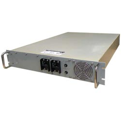
Additional Ruggedization to meet MIL-STD-901, MIL-STD-167, MIL-STD-810, and DOD-STD-1399: The System’s construction is extremely robust, and ruggedized throughout. All components and modules within the unit are mounted using additional steel brackets and heavy-duty stainless-steel hardware, which is then further secured using Loctite and RTV where required. All boards are conformal-coated (Acrylic MIL-I-46058 Type R) for maximum resistance to potential condensation and fungus growth. The unit was tested and qualified as follows:

MIL-STD-901D for Grade A, Class III, Type B Equipment
(mounted in shock-isolated rack attenuating to 20g/11ms max)

MIL-STD-167-1 for Type I Equipment

MIL-STD-810F:

Air Temperature per MIL-STD-810F Method 502.4, Procedure II
Steady State Temperature per MIL-STD-810F, Method 501.4, Procedure I (Constant Temperature) and Method 502.4,
    Procedure I
Temperature Shock per MIL-STD-810F, Method 503.4, Procedure II, Cyclic.
Thermal Shock testing per MIL-STD-810G, Method 503.5, Procedure I-D
High Temperature Storage per MIL-STD-810G, Method 501.5, Procedure I
Low Temperature Storage testing per MIL-STD-810G, Method 502.5, Procedure I
High Temperature Operating per MIL-STD-810G, Method 501.5, Procedure II
Low Temperature Operating per MIL-STD-810G, Method 502.5, Procedure II
Operational Humidity per MIL-STD-810F Method 507.4.
Humidity per MIL-STD-801G, Method 507.5, Procedure I
Storage and Transportation Humidity per MIL-STD-810F, Method 507.4
Salt Fog Atmosphere per MIL-STD-810F Method 509.4
Altitude per MIL-STD-810F, Method 500.4, Procedure I, Storage/Air Transport.
Operating and Non-Operating Altitude Testing per MIL-STD-810G, Method 500.5, Procedure II
Rapid Decompression per MIL-STD-810F, Method 500.4, Procedure III
Transit Shock per MIL-STD-810F, Method 516, Procedures IV, V and VI
Transportation Vibration per MIL-STD-810F, Method 514.5, Procedure II for loose cargo transportation
Transportation Vibration per MIL-STD-810G, Method 514-6, Procedure I, Category 20
Transit Drop per MIL-STD-810F, Method 516.5, Procedure IV
Transit Drop per MIL-STD-810G, Method 516.6, Procedure IV
Bench Handling per MIL-STD-810F, Method 516.5, Procedure VI
Bench Handling per MIL-STD-810G, Method 516.6, Procedure VI

DOD-STD-1399 Section 301A Table V –Design Limits for Ship Motion

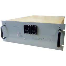
Internal EMI Reduction Package to meet MIL-STD-461: The design of this unit is specifically focused on reducing EMI emissions. The unit contains substantial internal filtering to minimize EMI emissions. Inputs which may be susceptible to transients are protected by several methods. The compact rack mount chassis is specifically treated with low surface resistivity finishes on the interior. All aluminum parts are treated with clear irridite. The steel parts are treated with zinc plate, followed by a clear chromate. Paint method via ANSI-61 gray is designed to assure excellent bonding of mating sheet metal parts. All input and output ventilation filters include metal honeycomb-style or mesh filters. The unit was tested and qualified as follows:

MIL-STD-461E: CE101, CE102, CS101, CS114, CS116, RE102, RS101, and RS103

Click here for Single Phase Lightweight Solid Frequency Converter Datasheet

Return to Homepage