
Precision AC Impedance & Transformer Test System
The system provides a controlled AC current stimulus, accurate voltage/current magnitude and phase measurement, allowing impedance and inductance to be measured under a defined operating current rather than only at small-signal conditions
Highlights
- Precision AC impedance and inductance measurement
- Controlled high-current AC excitation
- Measures voltage, current magnitude and phase angle
- LCRZ measurements under operating current conditions
- Transformer turns ratio and impedance testing
- Magnetising current measurement
- High-current inductor testing
- Wound component characterisation
- Low-phase-error current measurement
- 5 Hz to 100 kHz PAV measurement capability
- Computer-controlled measurement capability
- Configurable to suit current, voltage and frequency requirements
Description
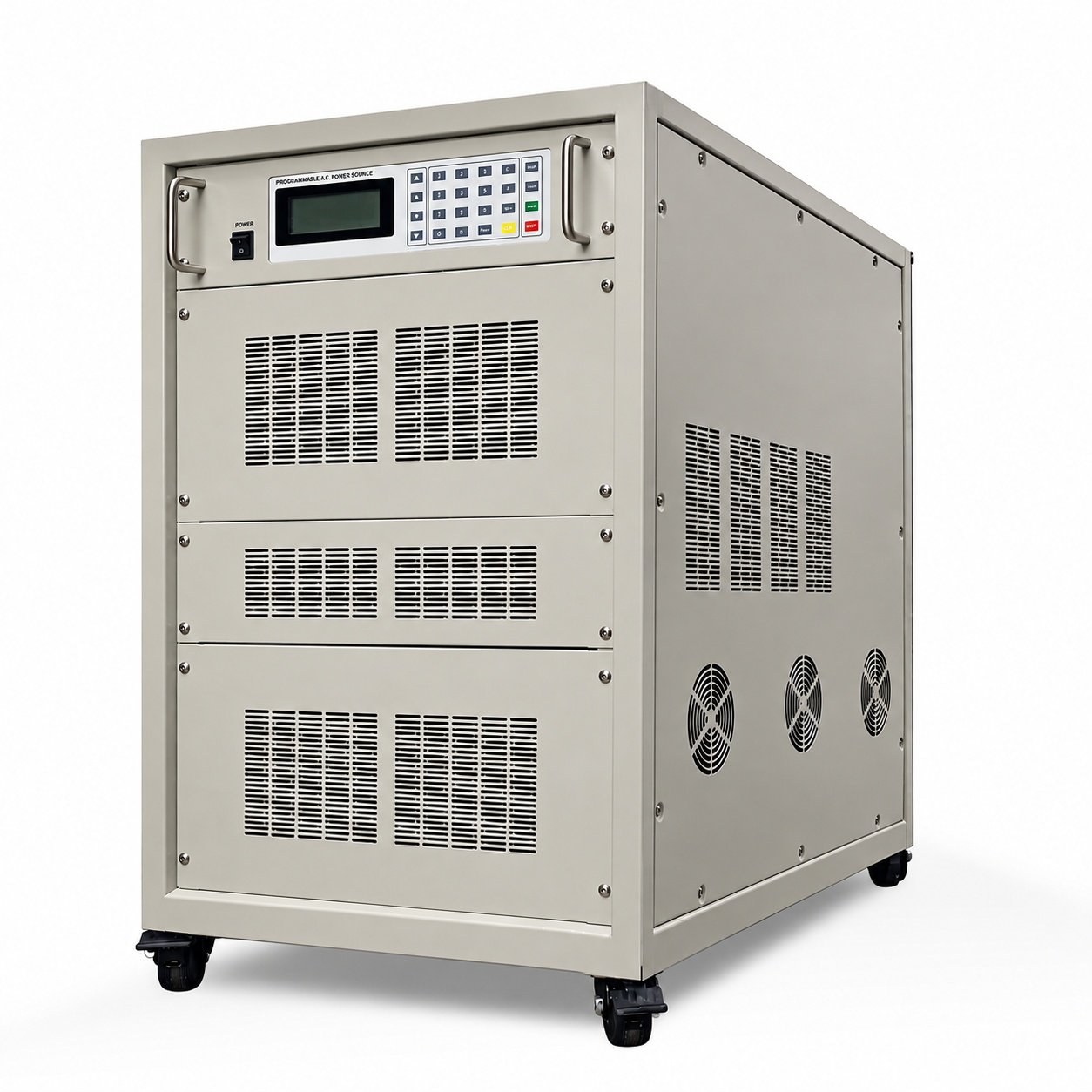
The Precision AC Impedance & Transformer Test System is an integrated measurement system designed for the characterisation of transformers, inductors, wound components and other magnetic devices where impedance and inductance need to be measured at a controlled AC current. The system combines three key functions, Precision AC current source, Precision current measurement, Voltage, current and phase measurement The PTK Precision Constant Current AC Power Supply provides a stable, programmable AC current to the device under test. Its linear amplifier architecture produces a low-distortion sine wave with programmable current and frequency. The current through the device under test is measured using a non-inductive co-axial current shunt. The co-axial shunt makes it particularly suited to applications where low phase error and wide bandwidth are important. The PAV1010A simultaneously measures two independent signals and determines their magnitude, phase relationship, in-phase and quadrature components, ratios and other parameters. Its phase measurement accuracy is specified down to approximately 0.02°, depending on frequency range. Together, these elements provide a controlled method of determining the electrical characteristics of a component while it is subjected to a defined AC current.
This system measures components closer to their real operating conditions. Conventional LCR measurements are often performed using relatively small test signals. For components whose characteristics vary significantly with current, this may not represent their behaviour under actual operating conditions. This integrated system allows impedance and inductance to be characterised at controlled, higher AC current levels, making it particularly useful for magnetic components, power inductors, transformers and wound components. The resulting measurements can be used to investigate parameters including Impedance, Inductance, Resistance, Reactance, Phase angle, Magnetising current, Turns ratio, Core-related losses, Copper-related losses, Current-dependent component behaviour
Applications
- Transformer Impedance Testing
- Transformer Turns Ratio Measurement
- Magnetising Current Measurement
- Transformer Winding Testing
- High-Current Inductor Testing
- Inductance Under High Current
- LCRZ Measurement
- Magnetic Component Testing
- Wound Component Testing
- Power Inductor Characterisation
- High-Current Impedance Measurement
- Impedance vs Current Testing
- Inductance vs Current Testing
- AC Resistance & Reactance Measurement
- Phase Angle Measurement
| Technical Specifications | |
|---|---|
| Model | |
| Capacity | |
| Phase | |
| INPUT | |
| Nominal Voltage | |
| Acceptable Voltage Range | |
| Frequency | |
| OUTPUT | |
| Nominal Voltage | |
| Rated Current | |
| Frequency | |
| Circuit Mode | |
| Memory | |
| Current Limit(I-LIM Set) | |
| Voltage Regulation | |
| Load Regulation | |
| Frequency Regulation | |
| Waveform | |
| Total Harmonic Distortion ( THD ) | |
| Overload | |
| LCD Display | |
| Efficiency | |
| Protection | |
| Operating Temperature | |
| Dimension:W×D×H(mm) | |
| Weight | |
Datasheet
Ordering Information
Example:
Contact Powertek today