CMC Rogowski Coil | High Accuracy AC Current Sensor
Non‑Intrusive, High‑Performance AC Current Sensor
The CMC Rogowski AC current probes for measuring HF Common Mode Currents in VFDs / VSDs and bearing spark erosion
Description
Variable Frequency Drives (VSDs) used to control AC motors can produce large high frequency voltages that may appear on the machine shaft. These voltages are the result of capacitive coupling of the applied PWM voltage to the motor windings. The voltages on the shaft can cause a flow of arcing currents through the motor bearings to ground.
The discharging currents, or bearing spark erosion current, can cause heating and even melting of the surface of the bearing raceways. The damage caused by bearing currents can lead to premature failure of the motor drive as well as costly maintenance and down time.
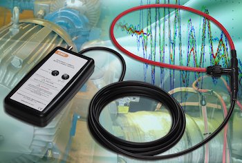
Powertek has developed a flexible, clip-around, current probe to measure these high frequency common mode currents which flow through a motor to ground via the bearings in large AC drive systems. The probe is a modified version of our highly successful, industry leading, CWT range of Rogowski current sensors.
The CMC current probe is an important tool for identifying the presence and severity of bearing spark erosion currents and common mode currents in large motor drives. It is designed for use by experienced personnel with knowledge of AC drive systems. Once identified, the CMC probe will give an engineer a reference measurement which can be used to evaluate the effectiveness of steps taken to mitigate against bearing currents.
Selection table
Selection Table for CMC On Current Probes
| CWT Mini Rogowski Coil Specifications | |||||||||
|---|---|---|---|---|---|---|---|---|---|
| Model | Sensitivity (mV/A) |
Peak current (A) |
Noise max mV p-p |
LF (-3dB) bandwidth (kHz) |
Typical LF (<1%) bandwidth (kHz) |
Peak di/dt (kA/uS) |
HF (-3dB) bandwidth (MHz) 1000mm coil length |
||
| CMC015 | 200.0 | 37.5 | 4.0 | 19.0 | 50.0 | 4.0 | 11.0 | ||
| CMC03 | 100.0 | 75.0 | 4.0 | 6.0 | 15.0 | 8.0 | 13.0 | ||
| CMC06 | 50.0 | 150.0 | 4.0 | 1.9 | 5.0 | 16.0 | 14.0 | ||
*1Distributed around the fL (3dB) bandwidth.
*2The high frequency bandwidth is in part dependent on coil length. Contact Powertek for other coil lengths
Specification:
| CMC Rogowski AC current Coil | |
|---|---|
| Peak Current | 10Apk to 150Apk |
| Output | ±7.5Vpk |
| High Frequency Bandwidth (-3dB) | up to 14MHz (CMC06 | 1000mm coil) |
| Low Frequency Bandwidth (-3dB) | Varies with model type (Refer Datasheet) |
| Accuracy | Calibrated to ±0.5% with conductor central in the Rogowski loop |
| Typical variation with conductor position ±0.3% of reading | |
| DC Offset | ±3mV max at 25°C |
| di/dt Ratings | Absolute max. 70kA/us (peak) |
| 1.5kA/us (rms) | |
| Operating Temprature Range | 0°C to +40°C (Integrator Elctronics) |
| -20°C to +90°C (Coil and Cable) | |
| Coil lengths | 500, 700 or 100mm (custom lengths available) |
| Coil Thickness | 8.5mm max |
| Peak Coil Insulation | 10kVpk |
| Cable Length (coil to integrator) | 2.5 or 4m (custom length available) |
| Power Supply | Option 'B': 1.5V Alkline Battery (selectable) |
| Option 'R': Rechargeable NiMH Battery (selectable) with on-board trickle charge circuitry | |
| plus default : 1.3mm socket for 12V (±10%) DC input | |
| Output Load | ≥100.0kohm (For rated accuracy) |
| Dimensions(H x W x D) | 183mm x 93mm x 32mm |
| 7.2in x 3.6in x 1.2in | |
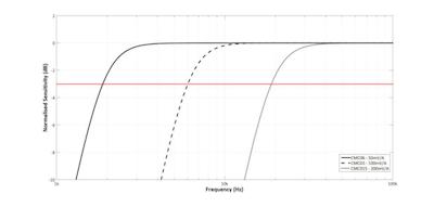
The low frequency bandwidth is set to attenuate any large fundamental frequency currents and magnetic fields. The CMC06 integrator has a gain of typically -90dB at 50Hz, this means that if there is a 100Arms, 50Hz current passing through the coil the output of the CMC will be <0.2mVrms.
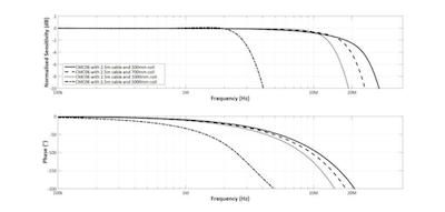
The high frequency bandwidth of the CMC current probe is determined by the coil length, the cable length and the integrator design. The high frequency bandwidth for each model is quoted for a 2.5m cable and a 1000mm coil in the specification table.
Typical High Frequency Response (Model CMC06 -- 50mV/A)
Showing the variation of HF performance with coil length, 500mm coil up to 5000mm coil
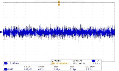
Noise Characteristics
The low noise integrator design allows better measurement accuracy of high frequency currents and enables a wide dynamic measurement range.
Typical noise – Model CMC03
Ch1 - CMC03/B/2.5/1000
Peak current range 75A, Sensitivity 100mV/A) Time base 2ms/div
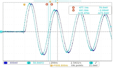
Delay Characteristics
The trace shows the CMC03 measuring a 2MHz sinusoidal current source compared with a traceable coaxial shunt measurement of the same current. There is a delay between the actual current and the output of the CMC which is predictable and is determined by the coil and cable length as well as the integrator design. The predicted delay for the CMC03B/2.5/1000 is 35ns.
2MHz damped sinusoidal current 16Apk
Ch1
CMC03/B/2.5/1000 (Peak current 75A, Sens. 100mV/A)
Ch2
Co-ax shunt 2GHz Timebase 200ns/div
Ordering
| Ordering | ||||
|---|---|---|---|---|
| Model: | Power Option: B-Battery / R-Rechargeable |
Cable length (m) | Coil circumference (mm) | |
| Description: 150A, 50mV/A, 4 AA Batteries, ac adapter, 2.5m cable from coil to integrator, 1000mm circumference coil | CMC06 | B | 2.5 | 1000 |
| Description: 75A, 100mV/A, 4 AA rechargeable Batteries, ac adapter, 12-24Vdc input, 2m cable from coil to integrator, 1000mm circumference coil | CMC03 | R | 2 | 1000 |
All CMC units are supplied with bnc-bnc cable, 12-24Vdc input, 4 AA batteries(selected from B or R ), power adapter, user manual, calibration certificate and carry case.
If you have any queries regarding the CMC or require specifications outside our standard ranges please do not hesitate to contact us.
Data sheets
CE Marked
Contact Powertek today