GIC DC current sensor for Geomagnetically Induced Currents [GIC] in Electrical Grids
CTH-GIC Current Sensors measure embedded DC and LF AC currents (very low frequency AC), in the presence of large AC currents at the utility power frequency
Highlights of the CTH-GIC Geomagnetically Induced Currents [GIC] Sensor
- High resolution (1000:1)
- Low residual dc offset
- Split-core for convenience
- Bi-directional sensing
- Non-contact current sensing
- Input/Output isolation
- Low power consumption
- Outdoor installation
- Wide temperature range
- Conduit attachment (Rigid 1/2” 12.7mm dia)
Description
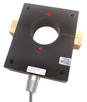
CTH-GIC transducers are able to measure DC currents including very low frequency ac, in the presence of higher levels of AC current at the power frequency. The CTH-GIC effectively attenuates the power frequency current allowing the DC and 'VLF' AC currents to be measured. This enables accurate measurement of Geomagnetically Induced Currents (GIC) on power grids and DC components potentially harming and degrading distribtion equipment. The device operates over a wide dynamic range and maintains low-level accuracy even after a large over-range. The GIC’s inherently low residual effect eliminates the need to degauss in all but extreme circumstances. The split-core enclosure, with captive hardware and outdoor rating, makes installation easy and does not require circuit interruption.
Why measure Geomagnetically Induced Currents? (GICs)
Geomagnetically Induced Currents (GICs) can result from geomagnetic storms, which is a type of space weather event in which Earth's magnetic field is disturbed by incoming magnetic solar material. Most GICs are triggered by coronal mass ejections, or CMEs, which interact with the magnetic field around Earth and cause it to temporarily "rattle". The quick-changing magnetic fields electromagnetically induce currents in long electrical conductor installations like grid and distrbution networks. GICs can flow also through railroad tracks, underground pipelines and power grids. In extreme cases, they can cause power outages like brownouts and in some cases blackouts.
Upsurge in Solar Activity: The recent upsurge in solar flare activity ushers in a new season of risk for critical grid infrastructure – particularly EHV Transformers. The Solar Flare Index for the current Solar Cycle 25 has increased from approximately 15 in 2020 -- to over 150 in 2023. This is comparable to levels present during the Coronal Mass Ejection activity in 1989
The Science of Solar Flare Impact on Earth
These “flares” release a shockwave of solar energetic particles, which in turn affect the Aural Electro-jet Currents. These Currents can reach millions of Amperes and impact the Earth’s magnetic field by inducing electric fields along the surface of the earth, creating potentials on the Earth’s surface
The Science of Impact to EHV Transformers
Grounded Neutral connections, common to many EHV transformers, complete a low resistance DC circuit that enables these DC currents to flow in the transformers. Unfortunately, the Transformer’s cores saturate at low levels of DC, enabling leakage flux, which in turn, produces eddy current heating in ferrous structural members. These can lead to winding overheating and insulation damage. In extreme cases, transformer failure occurs
Specifications
GIC Data SheetCurrent Input
- Current Range - See model selection
- Over-range (w/o damage) >8000A
- Bandwidth (1.5Hz low pass filter on output) dc to 1.5Hz
Output
Scaling- Models B, D, X5 0 to ±FS dc in = 0 to ±FS out
- Model EM -FS dc/0/+FS dc in = 4/12/20mAdc out
- Model E (unidirectional) 0-FS dc in = 4-20mAdc out
- Models E and EM 0-500Ω
- Model B 0-10kΩ
- Models D and X5 ≥2kΩ
- < 350ms (typical)
Instrument Power
- Standard 24Vac/24Vdc, ±10%
- Option “-12” 12Vac/12Vdc, ±10%
- Current nominal 80mA
- Current maximum 100mA
Accuracy
- Linearity, offset, setpoint and repeatability ≤0.5% F.S.
- Over-range residual offset 0.0007A/A of input current
(max offset = 350mA) - Linearity ≤0.1%F.S.
Dielectric strength / isolation
- Dielectric aperture: 2200Vac
- Instrument Power to output: 1kVdc
- Insulation class: 600Vac
Temperature
- Operating range -40°C to +85°C
- Temperature effect ±0.025%/°C
- Storage -40°C to +85°C
Physical
- Weight 2.0lbs
Model selection
Example: 600Adc Input 0-±1mAdc Outputs CTH-GIC-601B
| XXX | DC Range | Z | Output Type |
|---|---|---|---|
| 051 | ±0-50Adc | B | 0-±1mAdc |
| 101 | ±0-100Adc | D | 0-±10Vdc |
| 151 | ±0-150Adc | X5 | 0-±5Vdc |
| 201 | ±0-200Adc | E | 4-20mAdc |
| 301 | ±0-300Adc | EM | 4/12/20mAdc |
| 401 | ±0-400Adc | ||
| 501 | ±0-500Adc | ||
| 601 | ±0-600Adc | ||
| 801 | ±0-800Adc | ||
| 102 | ±0-1000Adc | ||
| 122 | ±0-1200Adc | ||
| 152 | ±0-1500Adc |
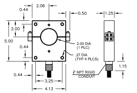
Case dimensions
Dimensions are in inches
Tolerance is ±0.03 inches
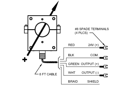
Connection Diagram
Contact Powertek today