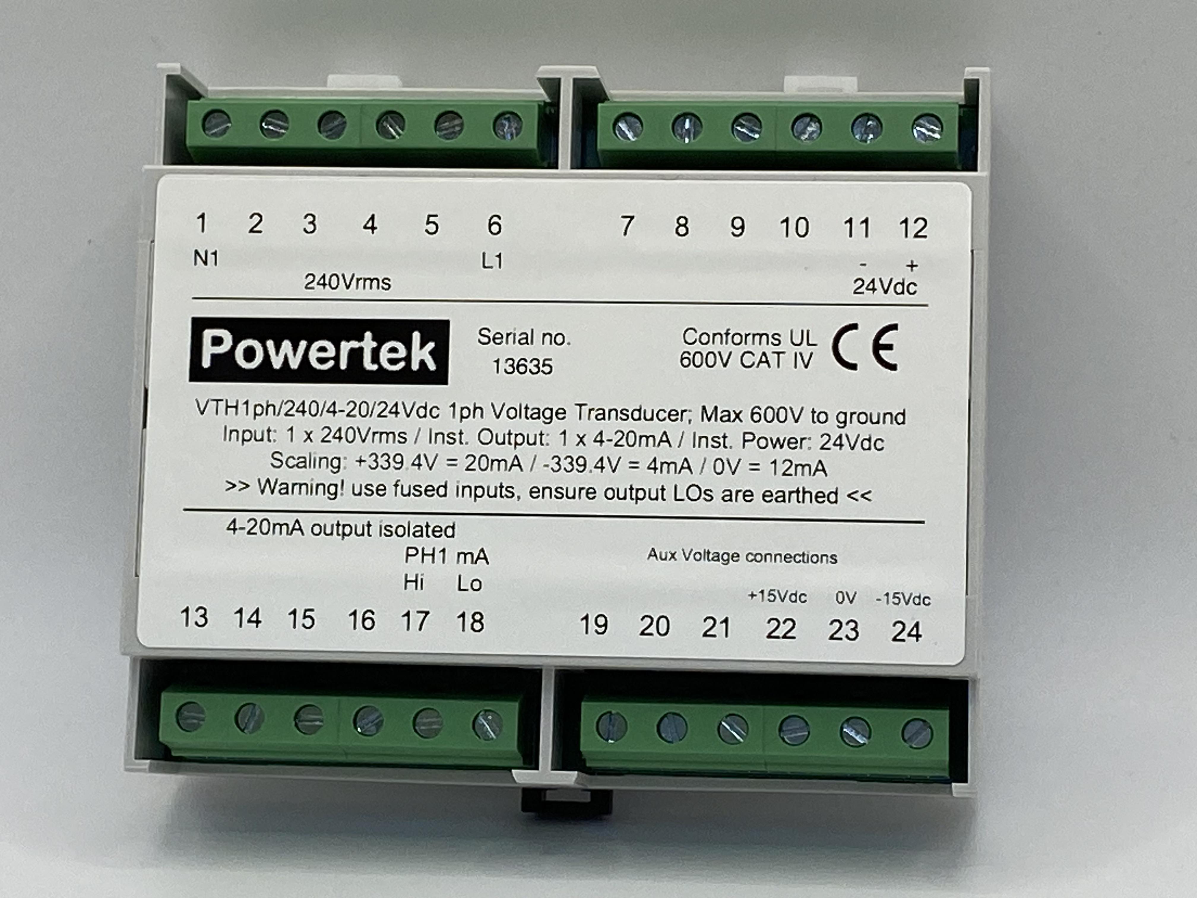
VTH1ph and VTHR1ph Single Phase Voltage Transducers for Voltage Sensing, instantaneous or rms with Modbus/RS485 outputs
The VTH1ph and VTHR1ph single phase voltage transducers convert dc or ac voltage to an isolated voltage or current loop output.
Description
The VTH and VTHR voltage transducers convert dc or ac voltage to an isolated voltage or current loop output. The Available VTH models cover the range from 50mV to 500Vrms, operation with a fast response capability, the Model VTHR offers true rms conversion DC-10kHz. VTH sensors are available in ac only or dc + ac configurations.
The sensor power input is designed to operate over a wide range associated with process control and sun-station auxiliary dc supply systems. Some typical applications are voltage monitoring in dc drives, process control, rail transpiration and circuit breaker trip coils. For all products, a NIST/NPL/UKAS traceable calibration certificate of conformance are available.
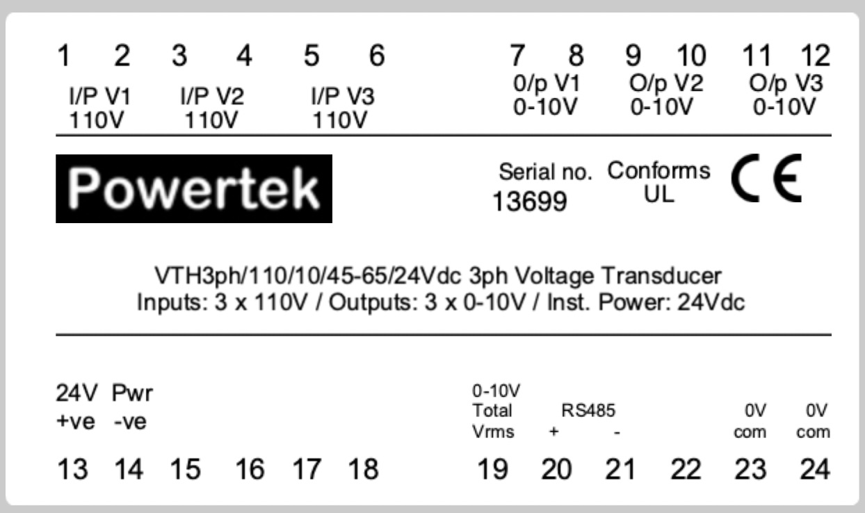
Safety and good working practice when using the VTH3ph and VTHR3ph voltage transducers
- Ensure that all personnel connecting and configuring the VTH are fully trained and conversant with electric shock and fire hazards associated with electricity supplies
- Ensure the circuit under test is switched off and isolated before connection
- Only use safety type cables for connections to the VTH probe. These cables are typically fitted with a 4mm safety type banana connector on either end. All connections should be insulated to prevent human contact
- Ensure that the VTH output (lo terminal) is connected to a grounded point on the scope/data logger/measurement system. Ensure it is a true ground and not just signal low
- Ensure that the maximum differential input voltage of (1000Vpk) and input voltage to ground (1000Vpk) are not exceeded
- Users should always work in pairs, both parties should be trained and familiar with medical procedures in the event of electric shock
- Ensure the circuit test is protected with over current protection
- During installation, avoid all mechanical stress to the VTH probe terminals
- Do not use the probe with the case open
- Ensure that the storage and operating conditions are clean and dry, do not use where there is risk of explosion
Product Specifications
- Available input ranges 0.333V to 600V ac or dc. Operational from 10% - 125% of range
- Outputs: 10V, 4-20mA and 4-12-20mA outputs available
- Auxiliary power input 12/24/48/110/230 Vdc or Vac. Max current draw 24Vdc 100mA max
- Fast response time <200uS (no filtering). Standard frequency range is DC-10kHz
- RS485 and Modbus interfaces transmit Vrms, Vrmsmax, Vmean, Vpk, Vpkmax, Vcf and frequency
- Certified accuracy better than <0.25% at +23°C ±5°C, traceable to NIST/NPL
- Internal gain and offset controls
- Galvanic isolation
- Working temperature range -10°C - 50°C
- Functional temp range –20°C - 70°C
- Rated working voltage insulation 1.5kVpk, flash tested 2.5kV for 1 minute
- Screw terminal input/output connections IP30
- Din Rail or Screw fixing
- CE Marked, UL94V0, IEC/EN61010 cat II, IEC348, DIN 57411
- Case IP50, terminals IP30 complies with IEC529
- 1 year warranty
VTH / Voltage range / Calibration frequency / output / power input
VTHR / Voltage range / ac+dc or ac / output / power input
Order code examples:
VTH / 200V / dc / 4-20 / 24Vdc
200Vdc input, 4-20mA output with 24V aux power input
Calibrated 0-200Vdc
VTHR/ 100V / ac+dc / 10 / 24Vdc
100V input, ac+dc coupled, 0-10V output with 24V aux power input
Calibrated 0-100Vdc
VTH / 300V / 60 / 4-20 / 24Vdc
300Vrmsinput, 60Hz max, 4-20mA output with 24V aux power input
Calibrated 0-300Vrms at 60Hz
VTHR / 50Vrms / dc-100 / 10 / 24Vdc
0-50Vrms input, frequency range dc-100Hz, 0-10Vdc output proportional to Vrms with 24V aux power input
Unless specified, the upper cut of frequency will be 10kHz
Contact Powertek today