
AC Impedance & Transformer Test System
The system provides a controlled AC current stimulus, accurate voltage/current magnitude and phase measurement, allowing impedance and inductance to be measured under a defined operating current rather than only at small-signal conditions
Highlights
- AC impedance and inductance measurement
- Controlled high-current AC excitation
- Measures voltage, current magnitude and phase angle
- LCRZ measurements under operating current conditions
- Transformer turns ratio and impedance testing
- Magnetising current measurement
- High-current inductor testing
- Wound component characterisation
- Low-phase-error current measurement
- 5 Hz to 100 kHz PAV measurement capability
- Computer-controlled measurement capability
- Configurable to suit current, voltage and frequency requirements
Description
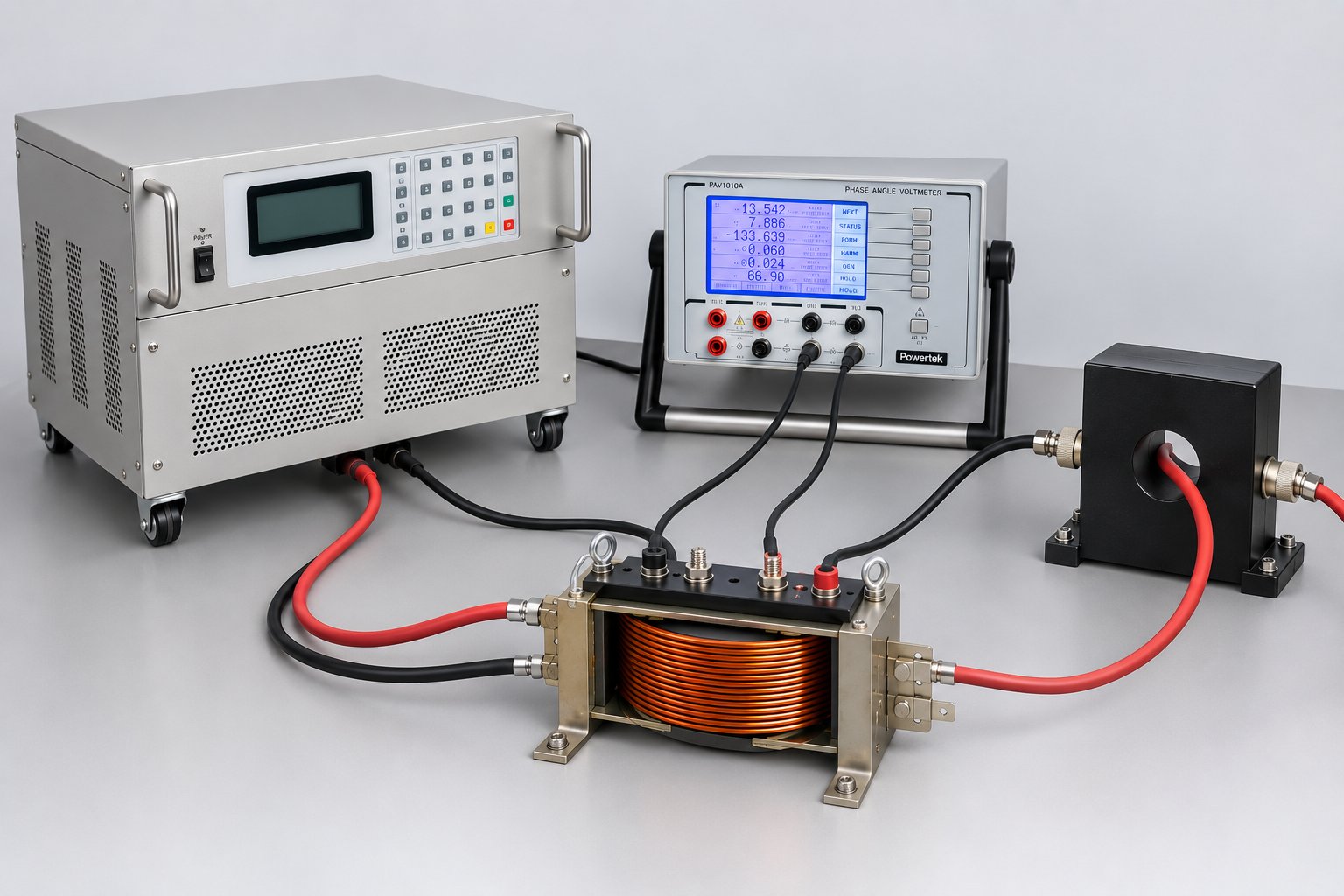
The AC Impedance & Transformer Test System is an integrated measurement system designed for the characterisation of transformers, inductors, wound components and other magnetic devices where impedance and inductance need to be measured at a controlled AC current. The system combines three key functions, Precision AC current source, Precision current measurement, Voltage, current and phase measurement The PTK Precision Constant Current AC Power Supply provides a stable, programmable AC current to the device under test. Its linear amplifier architecture produces a low-distortion sine wave with programmable current and frequency. The current through the device under test is measured using a non-inductive co-axial current shunt. The co-axial shunt makes it particularly suited to applications where low phase error and wide bandwidth are important. The PAV1010A simultaneously measures two independent signals and determines their magnitude, phase relationship, in-phase and quadrature components, ratios and other parameters. Its phase measurement accuracy is specified down to approximately 0.02°, depending on frequency range. Together, these elements provide a controlled method of determining the electrical characteristics of a component while it is subjected to a defined AC current.
This system measures components closer to their real operating conditions. Conventional LCR measurements are often performed using relatively small test signals. For components whose characteristics vary significantly with current, this may not represent their behaviour under actual operating conditions. This integrated system allows impedance and inductance to be characterised at controlled, higher AC current levels, making it particularly useful for magnetic components, power inductors, transformers and wound components. The resulting measurements can be used to investigate parameters including Impedance, Inductance, Resistance, Reactance, Phase angle, Magnetising current, Turns ratio, Core-related losses, Copper-related losses, Current-dependent component behaviour. The system also has an optional labview software PTK-Tx-Test.
Transformer Testing Applications
- Winding impedance testing
- Winding Turns Ratio Vrms
- Winding Turns Ratio In-Phase voltage
- Magnetising current measurement
- LCRZ measurements
- DC R
- High-Current Impedance Measurement
- Phase angle measurement between windings
- Cos (phi) power factor
- Shorted turn detection
- No load losses (W)
Wound Component Testing Applications
- High-current inductance testing
- Inductance measurement under normal operating conditions
- LCRZ measurements
- DC R
- Power inductor characterisation
- Impedance measurement under operating conditions
- Impedance vs full load current testing
- AC resistance & reactance measurement
- Shorted turn detection
Specifications
| Technical Specifications PAV1010A | |
|---|---|
| Channels/display | 2 isolated, 0.02° accuracy, 5 digits resolution 0.001° Null meter and Ratio |
| Measurement | For CH1 and CH2 Vrms, V in-phase, V fundamental, V quadrature, null meter, frequency, phase angle, Cos phi, THD% |
| Null Meter | 1uV sensitivity with frequency locked (from CH1 or CH2) |
| Voltage input range | 1mV to 350Vrms (500Vpk) |
| Phase input range | 0.000° to -360.000° |
| 0.000° to +360.000° | |
| 0.000° to ±180.000° | |
| Resolution 0.001° | |
| Frequency range | 5Hz to 100kHz |
| Common mode CMRR | 0.5Hz to 999.99Hz : 126dB |
| 1kHz to 5kHz: 110dB | |
| 5kHz to 32 kHz: 100dB | |
| 32kHz to 64kHz: 91dB | |
| Harmonic Rejection | 80dB (even and odd) |
| THD | ±0.05% |
| Max input | ±500Vpk |
| Input impedance | 2MΩ 20pF |
| Coupling | AC or DC |
| Averaging | 0.5, 3 or 10 seconds |
| General Specification | ||
|---|---|---|
| Frequency | Range: | 5Hz to 100 kHz |
| Accuracy: | ±0.1% (23°C ± 5°C) | |
| Inputs | Voltage Range (operational): | 1mV rms to 350V rms (500Vpk) |
| Current ranges using Options 02F/B: | 20mA - 2Arms range Opt. 02F/B 1R00 5Hz - 20kHz | |
| All voltage and current input combinations are possible: | 1.0Arms to 20Arms range Opt. 02F/B 0R01 5Hz - 20kHz | |
| Bandwidth: | DC-500kHz | |
| Isolation (inputs to ground): | 2000V | |
| Impedance: | 2MΩ and 20pF | |
| Environment | Temperature (Operating): | 0°C to + 50°C best accuracy 23°C ± 5°C |
| Temperature (Storage): | -40°C to +70°C | |
| Humidity (non-condensing): | 10% to 90% RH | |
| Dielectric Strength | Inputs to case or AC line input: | 2kV AC 50/60Hz 1 minute |
| Power supply to case: | 2kV AC 50/60Hz 1minute | |
| Power Requirements | Line input voltage: | 110V or 220V AC ± 10% |
| Line input frequency: | 50/60Hz | |
| Line input fuse: | 315mAT | |
| Line input conformance: | EN61000-3-2; EN61010 Class I; IEC801 Parts 1 to 4; EN55011 |
|
| Power consumption: | 25VA | |
| Mechanical | Weight: | 5kg (6kg in delivery packaging) |
| Dimensions (W x H x D): | 215mm x 144mm x 390mm | |
Datasheet
Ordering Information
Options:
- PAV1010A-Tx-1kVA
- PAV1010A-Tx-2kVA
- Software: PTK-Tx-Test version 2.1
Non-Inductive 4W Current Shunts:
- NICS 0R001
- NICS 0R002
- NICS 0R005
- NICS 0R01
- NICS 0R02
- NICS 0R05
- NICS 0R1
- NICS 0R2
- NICS 0R5
- NICS 1R0
Contact Powertek today